News
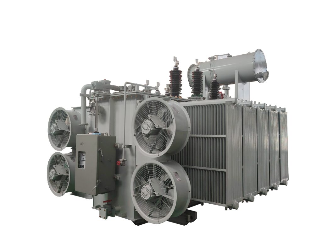
Transformer sizing directly influences system operational performance and safety. A properly sized transformer serves multiple core functions and prevents costly failures. This guide explains load calculation, voltage matching, efficiency considerations, and common sizing mistakes – helping you select the right transformer for your application.
A correctly sized transformer delivers several critical benefits:
In critical applications – hospitals, data centers, and continuous‑production factories – transformer reliability is paramount. Even a minor sizing error can lead to costly downtime, reduced production efficiency, and increased maintenance expenses.
| Consequence | Effect |
|---|---|
| Continuous overload | Excessive heat generation, accelerating insulation damage |
| Protective relay activation | Unexpected shutdowns, disrupting normal operations |
| Accelerated wear | Shortened service life, more frequent maintenance |
The first step in transformer sizing is determining the total load it needs to handle – typically measured in kilovolt‑amperes (kVA) . Engineers evaluate all connected equipment, operational patterns, and the system‘s power factor to obtain an accurate value.
Current load is calculated by summing the power consumption of all equipment, machinery, lighting, and other electrical devices connected to the transformer. This total load should reflect actual operational conditions – not theoretical maximums. In most facilities, some equipment runs continuously, while others operate intermittently.
Transformers must handle peak demand with ease. Peak load refers to the maximum electrical load a system may experience at any given time. However, not all loads reach their maximum capacity simultaneously. This necessitates the diversity factor – a value used to adjust the total load and derive the actual maximum load that aligns with real usage patterns.
By applying a reasonable diversity factor, engineers can ensure the selected transformer handles actual operational peaks without overestimating capacity requirements.
Consider an industrial facility with multiple large motors, a lighting system, and various small machinery. Engineers need to assess:
The base total load is adjusted using the diversity factor to derive the calculated peak load. Subsequently, a standard transformer model with a rating slightly higher than this value is selected – ensuring stable operation without the risk of overloading.
After confirming the load, verify that the transformer‘s voltage rating matches both power supply and load requirements – including primary and secondary voltages.
The primary voltage of the transformer should align with the input voltage from the power grid or generator. The secondary voltage must meet the operational requirements of the connected equipment.
Example: Step down high‑voltage grid power (13.8 kV) to standard equipment voltage (480 V).
Even if the transformer‘s voltage rating is accurate, consider voltage drop in the system. Voltage drop occurs when current flows through cables and other components. Excessive voltage drop can lead to reduced equipment performance or damage.
Guideline: In most industrial and commercial applications, voltage drop should be controlled within 5% of the rated value.
| Type | Application | Notes |
|---|---|---|
| Step‑down transformers | Facilities needing to reduce grid voltage | Most common type |
| Step‑up transformers | Renewable energy projects (solar, wind) | Boosts voltage for grid transmission |
| Autotransformers | Small‑scale voltage adjustments | Weaker electrical isolation – use with caution |
Transformer efficiency affects operating costs over decades. Inefficient transformers waste electrical energy as heat – increasing electricity expenses and cooling demands.
| Loss Type | Also Known As | When It Occurs |
|---|---|---|
| Core losses | No‑load losses | As soon as transformer is energized (24/7) |
| Copper losses | Load losses | Increases with current flowing through windings |
Both loss types impact the transformer‘s overall efficiency rating and operating costs.
High‑efficiency transformers reduce both core and copper losses – offering:
In large facilities with high utilization rates, energy‑saving benefits over the transformer‘s entire lifecycle are significant.
High‑efficiency transformers typically have higher procurement costs. However, reduced energy costs can fully offset the initial investment in the long run. For facilities operating continuously or near‑continuously, the payback period is usually only a few years.
| Step | Action |
|---|---|
| 1 | Calculate total connected load (actual operating conditions) |
| 2 | Apply diversity factor to determine realistic peak load |
| 3 | Consider power factor – adjust kVA requirement |
| 4 | Verify primary and secondary voltage compatibility |
| 5 | Account for voltage drop (≤5%) |
| 6 | Add 10‑15% safety margin for future expansion |
| 7 | Evaluate efficiency – balance initial cost vs. long‑term savings |
| 8 | Confirm environmental derating (altitude, temperature) |
Transformer sizing is not a one‑size‑fits‑all process. It requires a comprehensive assessment of current loads, peak demand, voltage compatibility, safety margins, efficiency indicators, and future expansion plans. By following these best practices, electrical engineers and project managers can select transformers that deliver optimal performance, meet safety and compliance requirements, and provide a strong return on investment.
Correct transformer sizing is an investment in long‑term reliability, efficiency, and safety. A properly adapted transformer can meet current electricity demand while flexibly responding to future changes – avoiding wasted funds due to excess capacity or equipment failures caused by insufficient capacity.
Contact a Xinghe representative today to learn more about our Transformer.