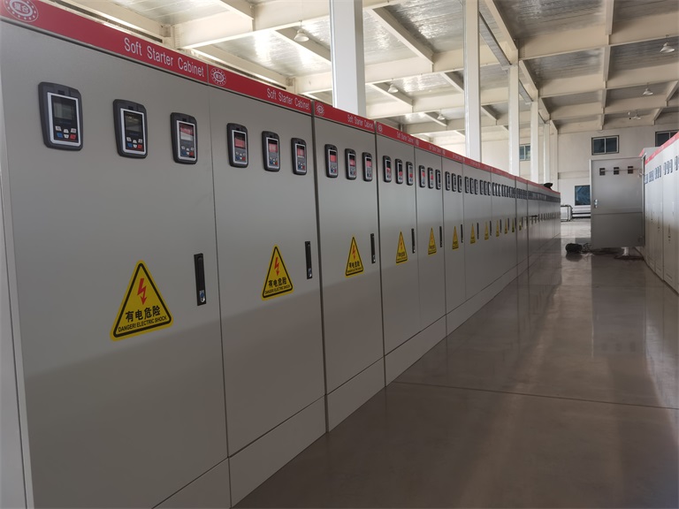
This series of control cabinets (boxes) integrates automatic control and manual control, and provides overcurrent, overvoltage, undervoltage, phase loss protection, and accident alarm functions. This guide explains how to correctly use, wire, and commission the equipment.
Before using this product for the first time, complete the following steps:
Review the electrical schematic diagram thoroughly.
Complete all wiring.
Adjust the setting values of corresponding components according to the motor's actual requirements.
After completing the above, you may start the equipment.
2. Automatic Control Mode
In automatic mode, the control cabinet starts and stops the motor based on commands from the liquid level controller.
Operation steps:
Turn on the power supply. The power indicator lights up.
Turn the transfer switch to the "Automatic" position.
Check whether the controlled motor follows the liquid level controller's instructions.
Working logic:
When liquid level reaches the control level → Corresponding level indicator lights up → Normally open contact of the liquid level control relay closes automatically → Secondary control circuit energizes → Motor starts → Running indicator lights up.
When liquid level reaches the stop level → Corresponding indicator lights up → Normally closed contact of the liquid level control relay opens → Secondary control circuit de-energizes → Motor stops → Running indicator turns off.
Therefore, automatic mode enables unattended liquid level control, suitable for water towers, tanks, wastewater treatment, and similar applications.
3. Manual Control Mode
In manual mode, the operator directly controls motor start and stop.
Operation steps:
Turn on the power supply. The power indicator lights up.
Turn the transfer switch to the "Manual" position.
Press the "Start" button → Motor runs → Running indicator lights up.
Press the "Stop" button → Motor stops → Running indicator turns off.
Manual mode is suitable for equipment commissioning, maintenance, or emergency operation when the automatic control system fails.
4. Protection Functions & Accident Alarms
Whether in automatic or manual control, this series of control cabinets provides multiple safety protections.
4.1 Over-Limit Level Protection
When the water level reaches the over-limit level, the over-limit level signal contact closes.
The secondary control circuit immediately de-energizes, forcing the motor to stop.
An audible and visual alarm (buzzer + alarm light) is activated.
4.2 Motor Accident Protection
If an accident occurs during motor operation (e.g., overload, short circuit, phase loss):
The accident indicator lights up.
The electric bell automatically sounds an alarm.
At this point, pressing the "Stop" button forces the motor to stop.
4.3 Comprehensive Protection Features
Protection Type
Function
Overcurrent
Prevents motor burnout due to overload
Overvoltage
Prevents voltage spikes from damaging components
Undervoltage
Prevents motor stalling due to low voltage
Phase loss
Prevents single-phase operation from burning the motor
Accident alarm
Alerts operators promptly to faults
5. Why Choose This Control Cabinet Series?
Two modes in one – Automatic and manual operation for flexible response to different conditions.