News
Target keyphrase: oil-immersed transformer for PV plant
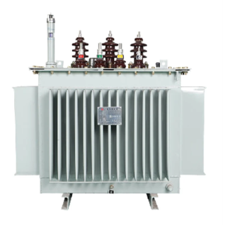
A oil-immersed transformer for PV plant is the core component that steps up inverter output voltage to medium or high voltage for grid connection. This guide explains why PV plants prefer oil-immersed over dry-type transformers, and how to select the right unit for your solar project.
Before choosing a oil-immersed transformer for PV plant, you need to understand its basic role.
In large PV plants, oil-immersed transformers serve two main functions:
Each generation unit uses a compact substation that integrates an oil-immersed step-up transformer with MV/LV switchgear. This ready-to-install unit raises inverter output to 35kV. Choose self-cooled, low-loss models per GB 50797.
After collecting medium voltage from all units, a main transformer further steps up to 110kV or 220kV for long-distance transmission. Oil-immersed units dominate here as well.
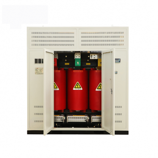
Compared to dry-type, oil-immersed transformers offer five key advantages for solar applications.
PV plants experience severe daily load cycles – full power at noon, zero at night. Oil-immersed units use mineral oil or natural ester as coolant. The oil's high specific heat capacity and circulation absorb heat spikes (e.g., from cloud-edge effects) without damaging insulation. Therefore, they handle thermal cycling better than dry-type.
Most PV plants are in deserts, coastal areas, or high-altitude regions. An oil-immersed transformer for PV plant has:
Result: up to 30 years of reliable service.
Instantaneous overloads are routine in PV plants. Oil's thermal mass provides strong short-term overload capability. Moreover, oil maintains high dielectric strength – suitable for HV and EHV (up to 500kV). Dry-type transformers typically max out at 35kV. Thus, oil-immersed is the only choice for large-scale and utility-scale plants.
Environmental concerns about oil leaks have led to natural ester insulating fluids (vegetable oil-based). Benefits:
This evolution makes oil-immersed transformers achieve high capacity, strong insulation, and environmental friendliness simultaneously.
Modern oil-immersed transformers for PV plants come with built-in online monitoring:
Choosing correctly optimizes levelized cost of electricity (LCOE). Follow these eight selection points.
| Feature | Oil-Immersed (incl. natural ester) | Dry-Type |
|---|---|---|
| Best for | Large outdoor plants, harsh environments | Rooftop, indoor, fire-sensitive areas |
| Cooling | ONAN or ONAF | Air natural or forced |
| Max voltage | Up to 500kV+ | Typically ≤35kV |
| Capacity | Tens of MVA | Usually <10MVA |
| Cost | Slightly lower at same capacity | Higher |
| Outdoor durability | Excellent (C5-M coating) | Limited |
Conclusion: For ground-mounted PV plants, choose oil-immersed.
Match transformer kVA to inverter total AC output. PV power factor is near 1.0 (resistive), not 0.8 like motors. Never blindly apply 0.8 factor – this oversizes transformer by 25%, increasing initial cost and long-term losses.
For local step-up transformers, off-circuit (de-energized) tap-changing (±2×2.5%) is preferred. It covers moderate voltage fluctuations.
Only consider on-load tap-changing (OLTC) when:
OLTC has lower priority for ordinary PV plants due to night-time no-load operation.
%Z must balance two risks:
Perform detailed short-circuit and voltage dip simulations to determine optimal %Z. Ensure compliance with grid fault ride-through requirements.
Follow local standards:
| Region | Standards |
|---|---|
| USA | IEEE, ANSI, NEMA, FERC; specifically IEEE C57.159-2016 |
| Europe | IEC/EN, VDE-AR-N 4105/4110, UK G99 |
| China/Asia | GB 50797-2012, NB/T 32004 |
Enclosure rating: Outdoor installation requires at least IP54 (dust-tight and water-resistant). C5-M corrosion coating is highly recommended.
Also ensure bidirectional power flow capability (for PV+storage), low THD, and DC injection prevention.
PV inverters produce harmonics (from IGBT PWM) and small DC components. These cause stray losses and extra heating. Therefore, for PV step-up transformers:
We are in a "transformer supercycle" with long lead times. When selecting a supplier:
The oil-immersed transformer for PV plant remains the mainstream choice for ground-mounted solar projects. Its advantages – excellent heat dissipation, harsh-environment tolerance, high overload capacity, and voltage scalability – are unmatched. With natural ester fluids addressing environmental concerns, oil-immersed transformers now offer high capacity, strong insulation, and green compatibility.
As the global PV market expands and supply chains tighten, scientifically selecting your oil-immersed transformer – focusing on capacity matching, voltage levels, grid compliance, and supplier reliability – is essential for grid interoperability, long-term safety, and lower LCOE.
Contact a Xinghe representative today to learn more about our Transformer.