News
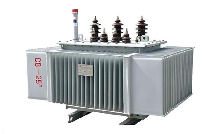
An amorphous alloy transformer uses a new type of energy‑saving core material that significantly reduces no‑load losses compared to traditional silicon steel transformers. This article explains the characteristics of amorphous alloy, the core structures used in amorphous transformers, and the key technical challenges – along with proven solutions for reliable manufacturing.
Amorphous alloy is a ferromagnetic material made from metals such as iron, nickel, cobalt, chromium, and manganese, with small additions of boron, carbon, silicon, and phosphorus. The material is produced by ultra‑rapid cooling (at rates of about 1 million °C per second), which freezes the atoms in a disordered, non‑crystalline state – hence the term “amorphous.”
| Property | Amorphous Alloy | Conventional Silicon Steel |
|---|---|---|
| Atomic structure | Disordered (amorphous) | Ordered (crystalline) |
| Strip thickness | ~0.025 mm | ~0.27–0.35 mm |
| Saturation flux density | 1.57–1.59 T | ~2.03 T |
| Recommended design flux density (3‑phase) | 1.25–1.35 T | 1.55–1.70 T |
| No‑load loss | Very low (70–80% lower) | Reference value |
Therefore, amorphous alloy is ideal for reducing transformer no‑load losses – but it requires careful design because its saturation flux density is lower than silicon steel.
Amorphous alloy is extremely sensitive to tensile and bending stress. Even small mechanical forces increase core loss. Consequently, we must account for this in the core and clamp design to maintain low loss performance.
Amorphous strip comes in limited widths – typically 142mm, 170mm, and 213mm. To build a transformer core, we stack these strips to achieve the required cross‑section. The core cross‑section is rectangular rather than stepped, which differs from conventional silicon steel cores.
| Type | Description | Typical Capacity Range |
|---|---|---|
| Three‑phase five‑column | Four wound cores forming five magnetic paths; most common structure | Up to 2500 kVA |
| Three‑phase planar wound core | Flat wound core arrangement | Smaller distribution transformers |
✅ For small distribution transformers (≤500 kVA, 10kV), we commonly use a four‑frame five‑column structure with four wound cores. For larger capacities, we stack eight wound cores in two rows (front and back) to achieve a larger cross‑sectional area – enabling ratings up to 2500 kVA with a single amorphous core.
To facilitate coil assembly, the core manufacturer designs the lower yoke as an open, multi‑layer interlaced joint. This opening allows the core to be split so we can slide coils over the legs. The joint must be on the lower yoke – not the upper – because the core cannot withstand pressure or stress after assembly.
| Parameter | Typical Value | Notes |
|---|---|---|
| Lamination factor | 0.82 – 0.86 | Depends on core stacking pressure |
| No‑load loss process coefficient | ~1.4 | Accounts for manufacturing tolerances |
| Thickness coefficient (core opening overlap) | 1.18 – 1.25 | Varies by manufacturer; confirm with core supplier before production |
Amorphous alloy sheets are brittle and prone to breakage. They shed small metal fragments that can cause insulation failure.
Solutions:
After we assemble the transformer body, we must turn the entire assembly 180° – but the open lower yoke cannot withstand stress.
Solutions:
The clamp must not only hold the core securely, but also protect it from external forces. This is very different from conventional S9 or S11 transformer clamp designs.
Design requirements:
Therefore, we include these protective measures in every amorphous transformer design.
| Aspect | Amorphous Alloy Transformer | Conventional Silicon Steel Transformer |
|---|---|---|
| No‑load loss | 70–80% lower | Reference |
| Core material cost | Higher | Lower |
| Saturation flux density | Lower (1.57–1.59 T) | Higher (~2.03 T) |
| Design flux density | 1.25–1.35 T | 1.55–1.70 T |
| Mechanical sensitivity | High | Low |
| Manufacturing complexity | Higher | Standard |
| Best application | Long operating hours (utilities, grids) | General purpose |
Contact a Xinghe representative today to learn more about our Transformer.