News
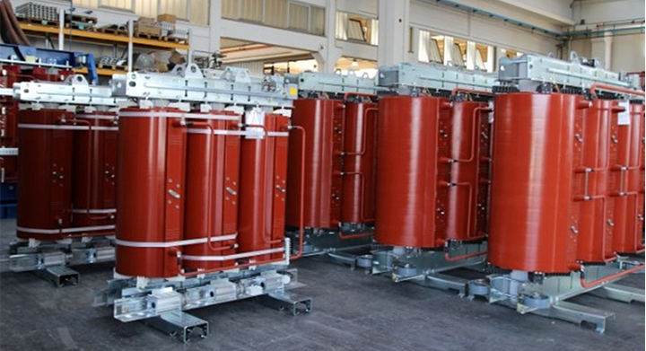
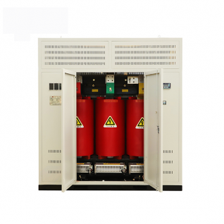
Dry-type transformers are widely used in indoor installations due to their fire‑safe, maintenance‑free design. However, like any electrical equipment, they can experience faults over time. This guide covers seven common faults in dry‑type transformers – from zero insulation resistance to discharge noise – and provides practical diagnostic steps and solutions to keep your transformer running reliably.
Symptom: The core‑to‑ground insulation resistance measures zero, indicating a direct metallic connection.
Possible Causes:
Solutions:
Symptom: The limit switch does not activate when the enclosure door opens, or it activates incorrectly.
Function: The limit switch is a safety device that triggers an alarm when any enclosure door is opened while the transformer is energized. Its contacts should close immediately upon door opening.
Solution:
Symptom: The temperature controller fails to:
Diagnosis:
If issues persist, contact the manufacturer‘s customer service for further assistance.
Symptom: Insulation resistance drops below acceptable values (typically < 1 MΩ per kV of operating voltage).
Cause: The most common cause is moisture ingress – insulation materials absorb moisture, reducing their resistance.
Solution:
Prevention: Keep the transformer in a dry environment (relative humidity < 70%) and avoid long‑term outages.
Symptom: Crackling or sparking sounds during the acceptance test (power‑frequency withstand voltage test).
Possible Causes & Solutions:
| Cause | Solution |
|---|---|
| Pull plate discharges at clamp tightening point | Tighten the clamp to ensure good conductivity between pull plate and clamp. |
| Spacer block creepage (especially in 35kV products) | Apply enhanced insulation treatment (e.g., add insulation layers or replace with higher‑grade material). |
| High‑voltage cable connection improper (too close to tap changer or angle connection tube) | Increase insulation distance and re‑tighten bolts. |
| Dust or particles on inner wall of high‑voltage coil (moisture absorption reduces insulation) | Clean the coil surface with dry compressed air or a soft brush. |
Symptom: Sparking occurs between the aluminum alloy panels of the enclosure and the ground rail when the transformer is energized.
Cause: Poor conductivity between enclosure panels – indicating a grounding failure.
Solution:
Symptom: Blackened or charred area on the high‑voltage coil angle connection tube.
Diagnostic Steps:
Conclusion: The burn is caused by an external short circuit that produced an arc and burnt the angle connection tube – not an internal coil fault. Replace the tube and correct the external issue.
| Fault Area | Prevention Measure |
|---|---|
| Core insulation | Keep transformer dry; avoid metal debris during installation |
| Limit switch | Test monthly during routine inspections |
| Temperature controller | Verify set points annually; calibrate sensors |
| Insulation resistance | Monitor with periodic megohmmeter tests; avoid damp environments |
| Discharge during testing | Maintain cleanliness; use proper insulation distances |
| Enclosure grounding | Ensure all panels have firm electrical continuity |
| Angle connection tube | Protect against external short circuits with proper overcurrent protection |
Contact a Xinghe representative today to learn more about our Transformer.